Information - Pressure tanks - hydrophore tanks
How to replace the bladder of pressure tank
How to replace the bladder of pressure tank
In water supply systems, pressure tanks, also called hydrophore tanks, hydro accumulators and Pressure vessels, are used to equalize pressure, prevent hydraulic shock and ensure smooth operation of pumps. Read more about pressure tanks, their different names and types in this article. The photo shows a bag-shaped diaphragm (bladder) of pressure tank:

Depending on the design solution, pressure tanks can be equipped with a membrane built perpendicular to the wall of the tank, or a bladder, fixed with a counter-flange on one end of the vessel, or a counter-flange and a special bulk head fitting at the opposite end of the tank. Perpendicularly built-in membranes are not replaceable, so the technical solution of both the tank and the membrane is designed so that the pressure tank works as long as possible. The manufacturer provides a 5-year warranty on such tanks, and they require almost no maintenance (e.g. checking the pre-charge pressure in the tank) during operation. Such pressure tanks are convenient and useful to install in systems with water without mechanical impurities, as it significantly prolongs the life of any pressure tank. Bladders are replaceable in all cases, and if they are damaged, it is not necessary to replace the entire tank. Such pressure tanks require periodic pre-charge pressure checks (see here) because the bladder has detachable connections to the tank, through which the air pressurized into the tank can leak over a longer period of time. Bladders are manufactured with a flange that serves as a sealing material between the tank body and the counter-flange. Bladders from each pressure tank manufacturer are designed with a flange that matches the pressure tanks of that manufacturer, so a bladder from one manufacturer usually does not fit the tank of another manufacturer.
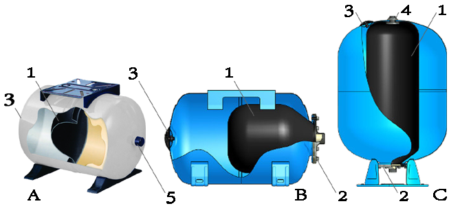
The figure below shows examples of pressure tanks with different membrane solutions: A – pressure tank with perpendicularly built-in membrane; B – pressure tank with bag-shaped membrane (bladder) fixed by counter-flange (2) on one end of the tank; C – pressure tank with bladder fixed by counter-flange (2) on one end of the tank and bulk head fitting (4) on the other end of the tank.

1 - bladder; 2 – counter-flange with connection to water supply; 3 – pre-charge air valve, closed with protection cap; 4 - bulk head fitting for bladder, fixed in pressure tank at both ends; 5 - connection to water supply line
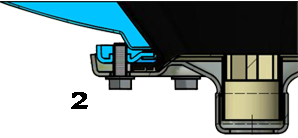
The counter-flange (2) attaches the bladder to the pressure tank inlet. It includes a thread to connect the pressure tank to the water supply system. For bladders that are attached to both ends of the pressure tank, a bulk head fitting (4) is also used to attach the bladder to the opposite end of the tank. The internal thread of the bulk head fitting is connected to the inside of the rubber diaphragm. If the threaded passage of the bulk head fitting is not used, it must be sealed with a plug during operation.
 |
 |
| Counter-flange | Bulk head fitting |
How to replace the bladder of a pressure tank - step by step
To replace the bladder of the pressure tank, follow these steps in sequence:
- Disconnect the pump from the power supply, close the shutoff valves on both sides of the pump (if any)
- Open one of the taps in the system so that excess water flows out and the system is depressurized
- Disconnect the pressure tank from the water supply or the pump
- Bleed the pressure tank completely via the air valve (3)
- Position the pressure tank so that the bladder counter-flange (2) is on top
- Loosen the bolts on the counter-flange (2) and remove the flange
- If the pressure tank has a bladder that is attached to both ends of the tank, also unscrew the bulk head fitting (4) located on the opposite end of the tank
- Pull out the old bladder and insert the new bladder into the tank
- For the bladder with attachment on both ends, first attach the bulk head fitting (4)
- Insert the new bladder so that its edge aligns exactly with the edges of the pressure tank opening and can be tightened firmly with the counter-flange (2)
- Install the counter-flange (2) and tighten the bolts evenly
- Pump the required pre-charge pressure into the pressure tank (see here)
- Make sure that no air escapes past the mounting flange(s) of the bladder
- Reconnect the pressure tank to the system or water pump.


